This dialog box is part of the command for creating pin objects. The parameters allow you to specify the quantity (up to a maximum of 32), spacing and name.
Quantity
Specify the number of objects to be placed. The amount of pins is always equal to one regardless of the value specified in this box if the option As Bus or the option Multiple pins is active.
Spacing
When there are more than one objects to place, the distance between the objects must be specified in this box. Select one of the proposed values to specify a spacing according to the grid or type directly the value of the spacing between objects.
Type
Select the pin type. The pin type is used during ERC.
Name, Number e Label
The name, number and label of a pin are constructed from the value of the prefix and the value of the index. The values of the index fields should only be specified when creating pin blocks.
The label assigned to a pin is displayed instead of the pin name when the pin name is set to invisible. Assign a value to the pin label only if the name to be displayed on the symbol is different from the actual name of the pin: for example in IEEE symbols.
Single Pin
To create a single pin, specify the name and number leaving the corresponding index fields blank. The pin name cannot contain the comma character.
Pin of a multi-part component
Multi-part components are components that contain multiple functional units of the same type. For example, component 74HC00 contains four two-input NAND ports. It is possible to represent this component with a single symbol representing the entire component but, in many cases, it is more convenient to be able to draw the four NAND doors separately, so that each door can be positioned independently of the others.
For this type of component a symbol representing a single part must be defined (for example, the symbol of a NAND port for component 74x00). For each pin in the symbol, the numbers and names that the pin assumes for each part must be specified, separated by commas.
For example, for component 74HC00, specify a value for the name and number, leaving the corresponding index fields empty.
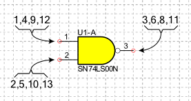
in the Number field you have to indicate: (1,4,9,12) for input A, (2,5,10,13) for input B and (3,6,8,11) for output Y.
in the Name field you have to indicate: (1A,2A,3A,4A) for input A, (1B,2B,3B,4B) for input B and (1Y,2Y,3Y,4Y) for output Y.
Pin with bus functionality
A pin with bus functionality represents a group of pins with a single graphic symbol. This type of pin allows you to create simplified symbols in which all pins corresponding to data or address lines are represented with a single pin. To specify that a pin has bus functionality you must tick the option As Bus.
In the Number field you must specify, separating them with commas, the numbers of all the pins belonging to the bus and in the Name field you must report, in the same order, the names.
For example, for the 27C64 component, specify a value for the name and number, leaving the corresponding index fields empty.
in field number you must indicate: 11,12,13,15,16,17,18,19.
in the name field you must indicate: D0,D1,D2,D3,D4,D5,D6,D7
Multiple pins
A multiple pin represents with a single graphic symbol a group of pins with the same electrical function and the same name. For example, some components have multiple ground line terminals (GNDs) that are internally short-circuited. To specify a multiple pin, check the Multiple pin option.
In the Number field you have to specify, separating them with commas, the numbers of all the pins and in the Name field you have to specify the name. Leave the corresponding index fields empty.
Pin Blocks
The complete value assigned to the pin consists of a fixed part and a variable index.
- Prefix
-
In this box the fixed part must be specified using the character '%' to indicate the position in which to insert the index. The index will be added to the prefix if its position is not specified.
- Index
-
In this box you can specify the initial value of the index to be hung on the prefix. If the value does not represent a number then the index will be alphabetical rather than numerical. The index value is automatically increased by one, you can specify a different value for the increment by separating it from the index with a comma. For example, for the increment use the value -1 to have a decreasing series.
For example:
if the Name field contains A% and the related Index field contains 0 the following pins are created: A0, A1, A2, A3 etc.
if the Name field contains A% and the related Index field contains 8,-1 the following pins are created: A8, A7, A6, A5 etc.
if the Name field contains A% and the related Index field contains 0,2 the following pins are created: A0, A2, A4, A6 etc.
if the Name field contains A1% and its Index field contains A, the following pins are created: A1A, A1B, A1C, A1D etc.
Options
- As Bus
-
A pin with bus functionality represents a group of pins with a single graphic symbol. This type of pin allows you to create simplified symbols in which all pins corresponding to data or address lines are represented with a single pin.
- Multiple pins
-
A multiple pin represents with a single graphic symbol a group of pins with the same electrical function. For example, some components have multiple ground line terminals (gnd) that are internally short-circuited.
- Hidden pin
-
In some components, such as those belonging to logical families, power supply pins may be hidden. Enabling this option specifies that the pin is hidden. When the netlist is created, all hidden pins are automatically connected to other hidden pins with the same name and to connections with the same name.
- Visible line
-
When this option is enabled, the line connecting the two characteristic points of a pin is visible.
- Number visible
-
Determines whether the pin number is visible.
- Number in vertical
-
Specifies the orientation of the number when the pin is placed vertically.
- Name visible
-
Determines whether the pin name is visible.
- Name in vertical
-
Specifies the orientation of the name when the pin is placed vertically.
- Pin not electrically connected
-
When this option is enabled, it is specified that the pin is not electrically connected and should be ignored during the ERC.
- Skip if hidden
-
The pin is ignored if this option is enabled and the pin is hidden.
- Only graphic object
-
If this option is active, the pin will be created without electrical functionality. A non-electric pin is only a graphic object and must be used when the symbol requires the presence of some pins for representative purposes only.
- Swap the positions of the name and number
-
Swap the positions of the number and the name.
- Automatic number and name position
-
Indicates whether the name and pin number should be repositioned automatically when the pin is rotated.
- Show only first pin number
-
When this option is enabled for a Multiple or Bus pin, only the first pin number is shown instead of showing all pin numbers.
Style
Select the style from those listed or create a new one.